Shielding Effectiveness
Description
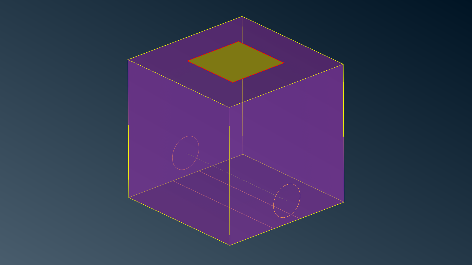
This test case pictures an almost closed cavity, the box, opened on the top by a square-shaped thin slot delimiting a door.
We wish to compute the electromagnetic field inside the cavity for a given incident plane wave.
A victim cable is located at the bottom of the cavity and is connected to it at both ends. A local impedance is placed on the middle of the wire to model an equipement.
Some virtual junctions connect the door and the box across the slot to model rivets/bolts.
Volumic domains
This model contains only the exterior domain EXT as homogeneous volumic dielectric domain because the
cavity is not completely closed.
Surfacic interfaces
Both the box BOX and the door DOOR are made of resistive (finite conductivity) metallic materials.
Wires
A wire models the cable and joins two opposite sides of the box.
Local values
Local values are used to model passive impedances or active voltage sources on local elements. In this model we consider passive local impedances on the wire (equipment) as well as on the virtual junctions (rivets).
download
shielding-effectiveness.ansa.gz (ansa v24.0.0)
CAD and mesh tips
Wires are meshed with NASTRAN CBEAM elements. Some assumptions must hold on the
lineic elements size and radius (see below) for the model to hold.
Junctions between the wire and the box are automatically handled by the plugin.
The virtual junctions are not contained in the CAD, they are added interactively using the plugin.
For low frequency computations it is more the geometry that drives the mesh length rather than the wavelength. Special attention is given to local refinement around:
the slot border where the current can vary rapidly;
junctions between the sheet and the wires (to do so one can draw a disk around wire extremities, then assign a small mesh size on that disk, finally loosen the transition by joining the perimeter of the disk);
the surface neighborhood of the wire to capture wire-surface coupling.
Simulation setup
Physical properties
The volumic domain is naturally characterized by air properties \(\varepsilon=\varepsilon_0\) and \(\mu=\mu_0\), that is, relative permittivity and relative permeability of 1.0.
The resistive surface materials are characterized by:
Name |
Conductivity \(\sigma\) [S/m] |
Thickness \(d\) [m] |
Relative permittivity \(\varepsilon\) |
|---|---|---|---|
box |
4e6 |
0.002 |
\(\varepsilon_0\) |
door |
3e5 |
0.001 |
\(\varepsilon_0\) |
The wire is characterized by:
Name |
Lineic impedance \(\rho\) [Ohm/m] |
Radius \(r\) [m] |
|---|---|---|
cable |
0.0 |
0.005 |
The local values are featured as passive impedances. One of them is on the wire (equipement). The others are spread on the boundary of the slot (rivets). They are characterized by:
Name |
Impedance \(Z\) [Ohm] |
|---|---|
equipement |
1e-2 |
rivet |
1e-3 |
Illumination
A normalized plane wave of magnitude 1 V/m illuminates the box from \(\theta\) = 0.0° and \(\phi\) = 0.0° with both vertical and horizontal polarizations.
Note
Plane waves are linearly polarized. Choosing both vertical and horizontal polarizations allows to recombine for any polarization.
We are interested in the low frequency range from 1 Hz to 100kHZ using a logarithmic spacing with 1 frequency per decade.
Note
Enable the low frequency mesh preprocessing option.
Observation
We can compute the near field in a cut plane inside the box. For instance a 2D grid defined by:
#  x   y   z
0.06 0.3 0.06
0.54 0.3 0.06
0.06 0.3 0.54
# N1 N2
60 60
We also want to compute the current that flows through the local values (equipement and rivets).
Results
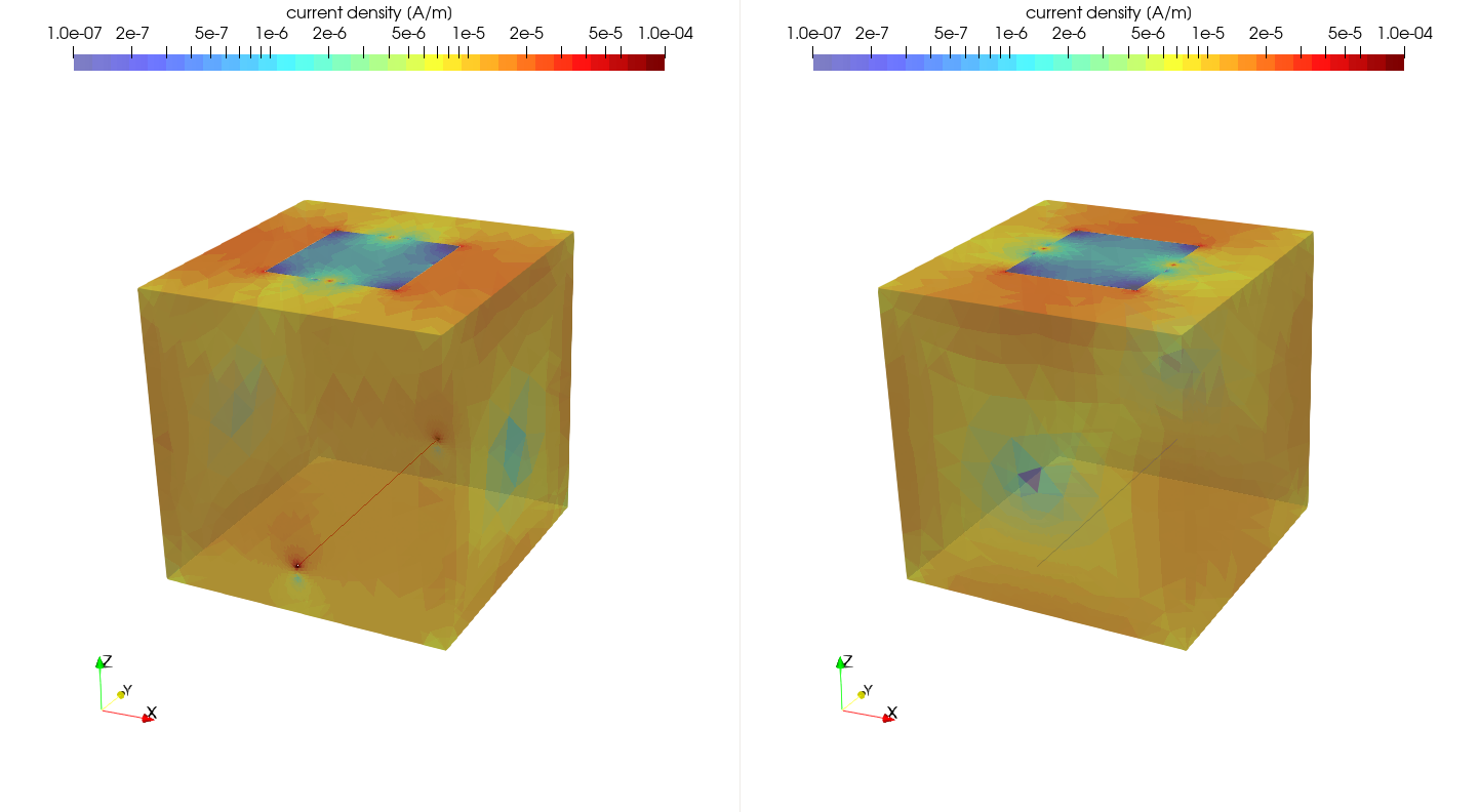
Current density for both horizontal (left) and vertical (right) polarization at 1 Hz. The cable is more excited when aligned with the incident wave. One can see the current following through the rivets (virtual junctions).
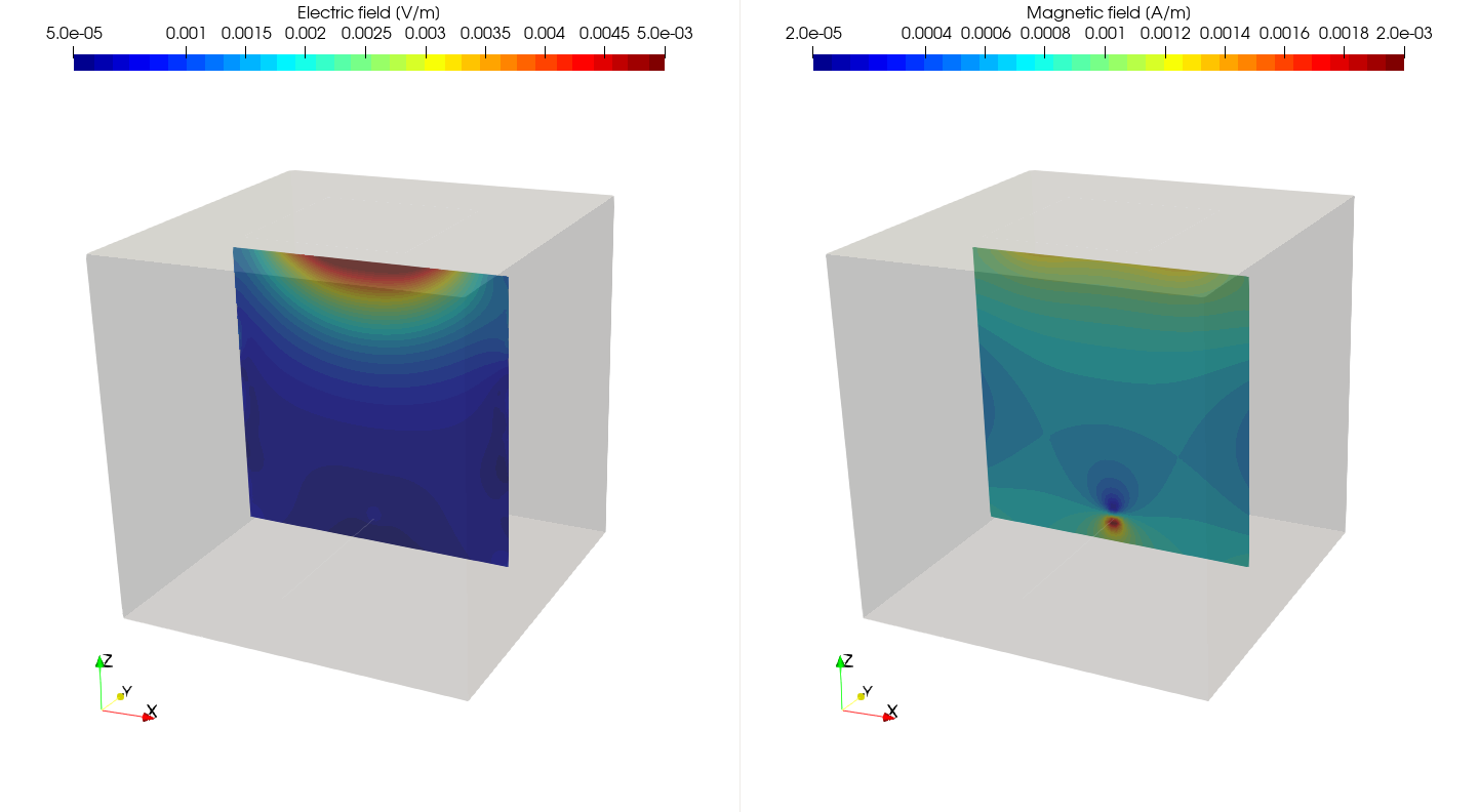
Electric field \(E\) (left) and magnetic field \(H\) (right) inside the cavity at 1 kHz.
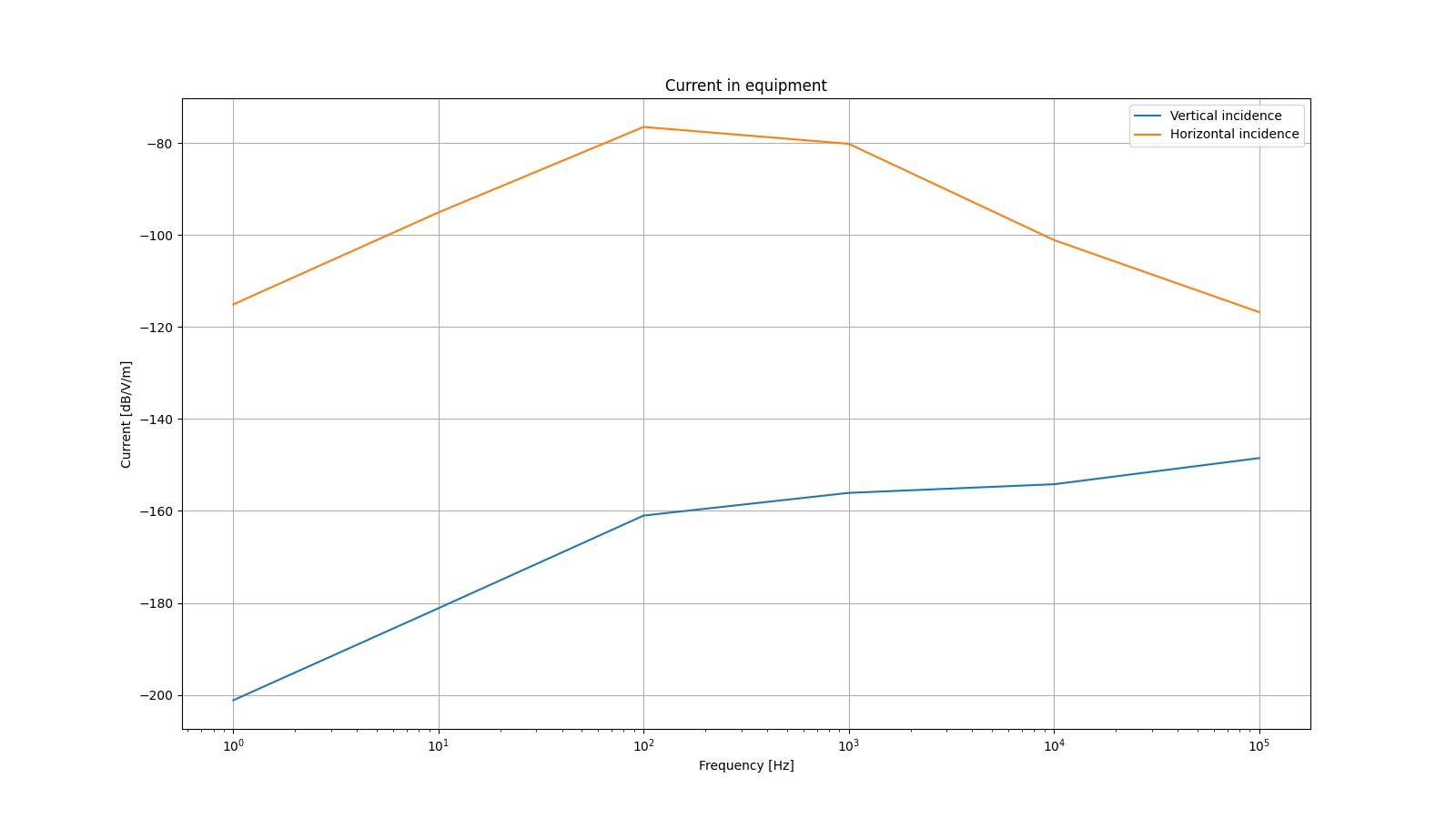
Current at equipment. Victim equipment is more sensitive to a vertical incident aggression.
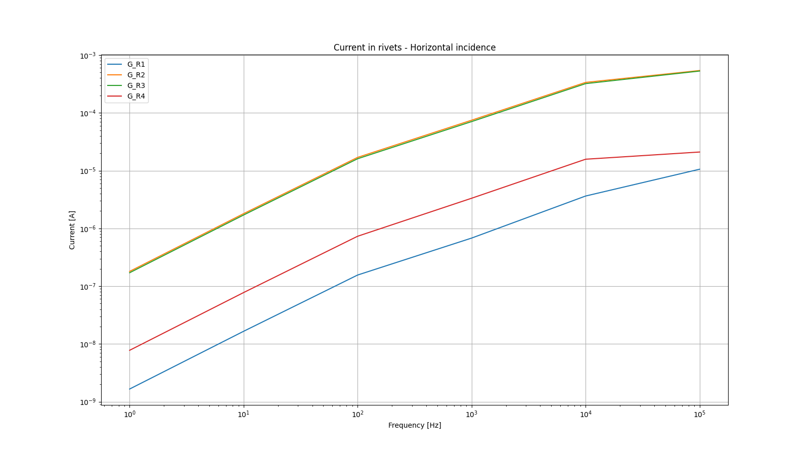
Current at rivets for horizontal incident aggression.