Huygens
Description
This example showcases the usage of a Huygens surface as a source. A Huygens field box typically comes from measurements or simulation of an antenna model subject to Industrial Property. They are used for studying antenna siting on some platform or support (vehicles, buildings, etc.).
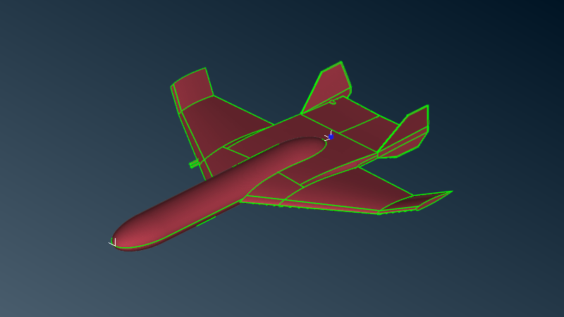
In this case, the support is a simple all-metallic UAV model inspired from [1]. We wish to compute the surface current density on the platform as well as the far field radiated by the structure illuminated by the Huygens box.
This Huygens box has been simulated using ASERIS-BE. It contains the near field of a simple antenna on an infinite ground plane. It must be placed on the UAV on a locally metallic surface.
The Huygens source can be found in the huygens_source directory in the following formats:
ASERIS: native format of near field computation with ASERISVTU: paraview.vtuformat of near field computationMvG: measurments format from MvG [2] as a text file, containing the mesh and the values of the EM field on the surface.
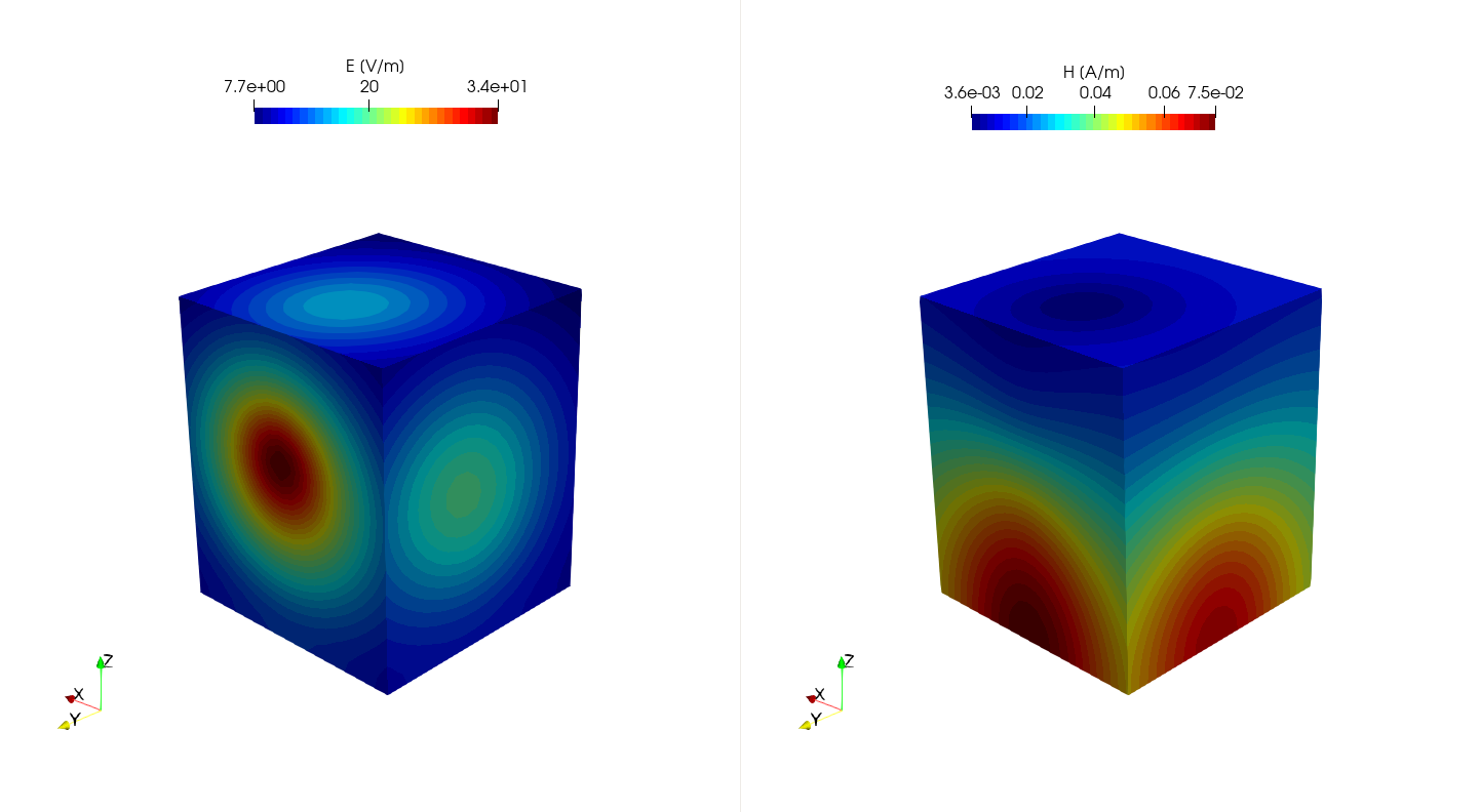
Huygens source. EM field radiated by the antenna on a surrounding surface called the Huygens surface.
Note
ASERIS and VTU formats allow for any shape as long as it is open on the \(z=0\) plane if the antenna lies
on a ground plane. However, for the MvG format the Huygens surface must be a box.
download
huygens.zip (ansa v24.0.0)
CAD and mesh tips
A Huygens box comes with its frequency, the one for which the EM field has been computed/measured. It is here equal to \(750\) MHz for which the wavelength is about \(40\) cm. We use a mesh length of \(\lambda / 10 = 4\) cm.
It will be placed on the platform mesh and locally remeshed by the plugin. If the transition between the meshes is too abrupt (for ASERIS-BE, the more balanced are the triangles, the better is the mesh), we can tune the remesh parameters to allow a better local refinement. Smoothing can also come in handy for antenna siting on a curved part of the platform.
Simulation setup
Physical properties
The exterior volumic domain is naturally characterized by air properties \(\varepsilon=\varepsilon_0\) and \(\mu=\mu_0\), that is, relative permittivity and relative permeability of 1.0.
We are not interested in the interior UAV domain so we can consider this volume as metallic.
Illumination
Make sure you provide the same frequency as the one of the Huygens box, (here 7.5e8 Hz).
The plugin will help you import and place the Huygens box on the platform. The main stages are:
Select the appropriate supported format and load the corresponding Huygens source file
Place the source
Stitch and remesh
Observation
We wish to compute the current density as well as the far fields on the whole sphere.
Solver
For such a large case select the H-Matrix solver. For better precision, we can change the default assembly and recompression tolerances to \(5\cdot 10^{-5}\).
Enable FMM for post-processing computations.
Results
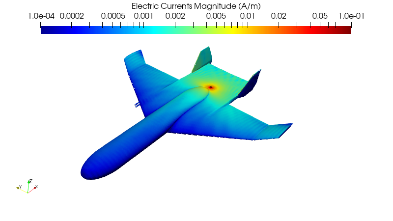
Current density on the UAV illuminated by the Huygens source.
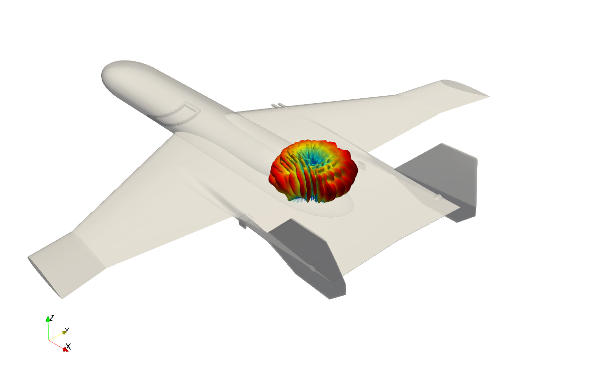
3D far field pattern positionned at the Huygens source location.
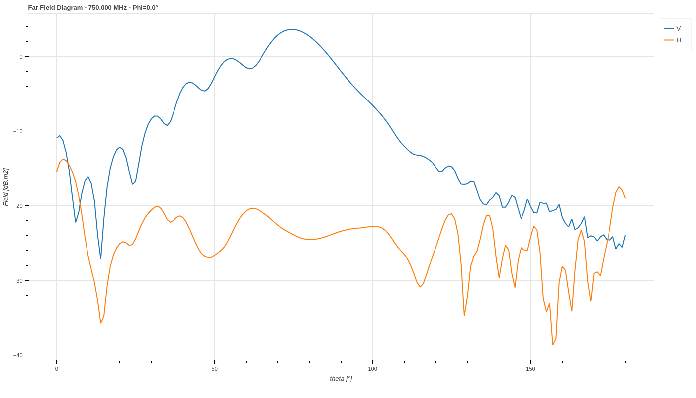
Far field diagram for \(\phi=0\) °.