Crosstalk
Description
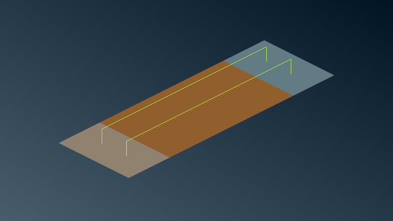
This case pictures a crosstalk problem between an aggressor cable and a victim cable. They are running along a path above a finite ground plane.
Volumic domains
This model contains only the exterior domain EXT as homogeneous volumic dielectric domain.
Surfacic interfaces
The model is made of a conductive sheet sheet between perfect conducting (PEC) extremities PEC_left and
PEC_right.
Wires
Two wires join each PEC sheets, one is the aggressor, the other the victim. Junctions between the wires and sheets are automatically handled by the plugin.
Local values
Local values are used to model voltage sources and equipments on elements. In this model, they are placed on each vertical branch of the wires. They are considered here as general network ports.
download
crosstalk.ansa.gz (ansa v24.0.0)
CAD and mesh tips
Wires are meshed with NASTRAN CBEAM elements. Some assumptions must hold on the
lineic elements size and radius (see below) for the model to hold.
The mesh is refined around the material discontinuity between the conductive sheet and PEC extremities.
Special attention is given to local refinement around junctions between the sheet and the wires.
Simulation setup
Physical properties
The volumic domain is naturally characterized by air properties \(\varepsilon=\varepsilon_0\) and \(\mu=\mu_0\), that is, relative permittivity and relative permeability of 1.0.
The conductive sheet is characterized by:
Name |
Conductivity \(\sigma\) [S/m] |
Thickness \(d\) [m] |
Relative permittivity \(\varepsilon\) |
Relative permeability \(\mu\) |
|---|---|---|---|---|
sheet |
4e6 |
0.002 |
\(\varepsilon_0\) |
\(\mu_0\) |
The wires are characterized by:
Name |
Lineic impedance \(\rho\) [Ohm/m] |
Radius \(r\) [m] |
|---|---|---|
aggressor |
1e-3 + 0j |
0.001 |
victim |
1e-4 + 0j |
0.002 |
Local values are defined as active voltage generator:
Name |
Impedance \(Z\) [Ohm] |
Electromotive force e.m.f. \(E\) [V] |
|---|---|---|
Aggressor_PORT_1 |
0.0 |
1.0 |
Aggressor_PORT_2 |
1e-4 |
1.0 |
Victim_PORT_3 |
0.0 |
1.0 |
Victim_PORT_4 |
2e-3 |
1.0 |
Warning
If the name of a local value contains PORT_ followed by a number it is tagged by the solver as a port and can
thus be used after the 3D fullwave computation for exact network model reduction using the computed admittance
matrix. In this case the local value must be an active voltage generator.
Advanced fast multiport computations using the ASERIS-MULTIPORT tool are thus possible for many applications
such as statistical analysis, optimization, etc. This tool will be introduced later.
Note
Many other useful formats such as frequency-dependent impedances and/or e.m.f. are handled by the solver. We set them here with constant values for the sake of simplicity. We refer to the plugin for the various possible formats.
Illumination
Each voltage generator is treated as an independent source, that is, there will be as many solutions as voltage sources.
The simulation is performed for a linear frequency sweep from 10 MHz to 100 MHz with a step of 10 MHz.
Observation
We are interested in the current through ports when Aggressor_PORT_1 is on.
Results
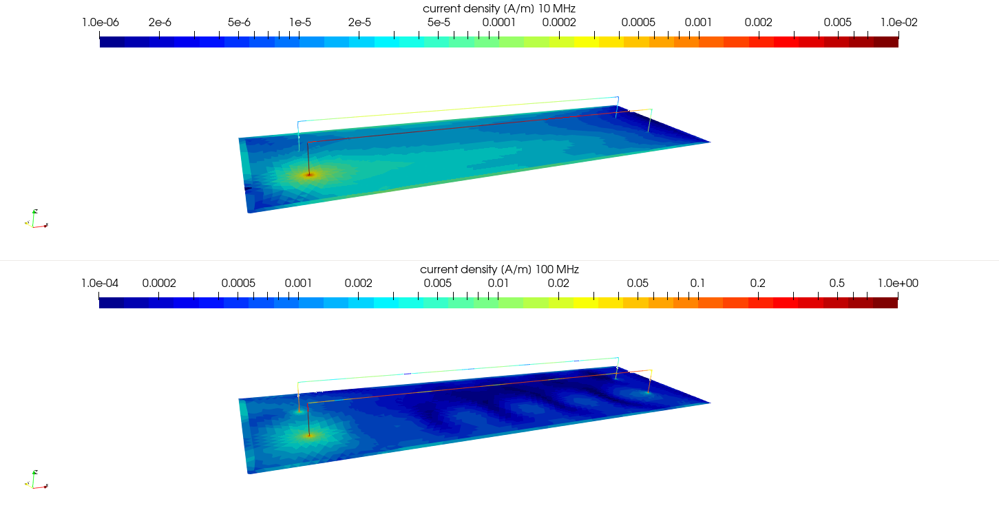
Current density for 10 MHz (above) and 100 MHz (under).
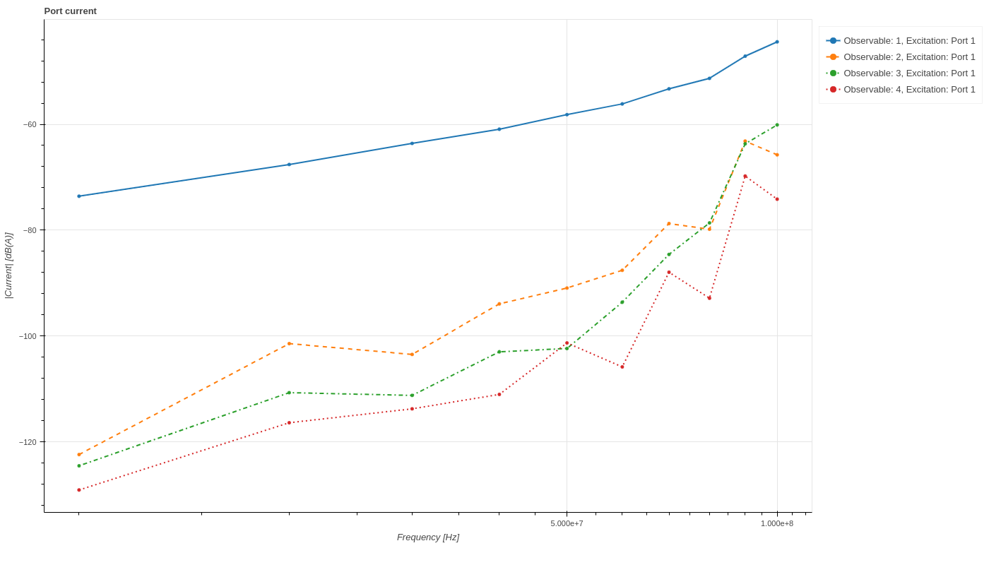
Current at ports. Blue solid line represents the current through the active generator Aggressor_PORT_1.